


Shotcrete Spray Slowing Down and Pulsating? The Problem Could Be in the Pipe Bends
A pulsating shotcrete spray is usually blamed on the mix, but the real culprit may be the shotcrete pipe bends. Imagine an operator working inside an underground mine tunnel. The spray, initially stable, suddenly becomes intermittent and then starts surging violently. Water and cement proportions are checked again, aggregate size is inspected, and compressor pressure is increased. Sometimes the problem disappears, only to return the next day.
Few people suspect one component that has actually been a potential culprit all along: the pipe bends. An experimental study found that a bend can reduce shotcrete velocity by roughly 30–40% (Chen et al., 2025). This article summarizes the findings and what you can check in the field.
Why Shotcrete Flow Inside the Pipe Is Not Uniform
From the outside, a shotcrete pipeline may look uniform. The diameter is the same, the steel is the same, and the air comes from the same compressor. Inside, however, the material behaves differently along different sections of the pipeline.
A research team from Shandong University of Science and Technology recorded the flow of stiff shotcrete through transparent acrylic pipes using a high-speed camera. Their test pipeline was 36 meters long and included one 90° bend. They observed three different flow patterns (Figure 1):
- Initial section (near the inlet): the material moved along the bottom of the pipe, with coarse aggregates rolling along the lower surface.
- Straight section farther downstream: most of the material was lifted and suspended by the airflow.
- After the bend: the third flow pattern, described in the next section (Chen et al., 2025).
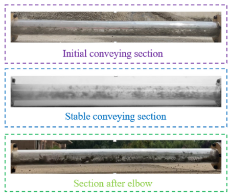
Figure 1. Particle flow characteristics in the initial section, stable section, and section after the bend
What Happens After a Shotcrete Pipe Bend?
At the bend, the material collides with the pipe wall. Its velocity decreases by approximately 30–40%. More than 70% of the coarse aggregate temporarily settles at the bottom of the pipe before being lifted again by the swirling airflow downstream of the bend (Chen et al., 2025).
It is similar to traffic on a highway. Vehicles move in an orderly flow on a straight section, but when they encounter a sharp bend, traffic slows down and begins to accumulate before moving forward again in groups. Inside the pipe, coarse aggregates behave in a similar way: some are left behind and then catch up in waves. As a result, the shotcrete emerging from the nozzle (the end of the hose where the material exits) can feel pulsating or intermittent.
Pressure loss at the bend and initial section
The bends also consume pressure. Per unit length, pressure loss at the bend is approximately 2–3 times higher than in a stable straight section. In the initial section, the pressure loss is even greater, at around 3–4 times higher. These sections are short compared with the total pipeline length, but they experience the greatest flow resistance (Chen et al., 2025).
Pressure measurements in the 51 mm pipe
Pressure measurements support this observation. In the 51 mm diameter pipe, the results were: A similar pattern was observed across all three pipe diameters tested (Chen et al., 2025).
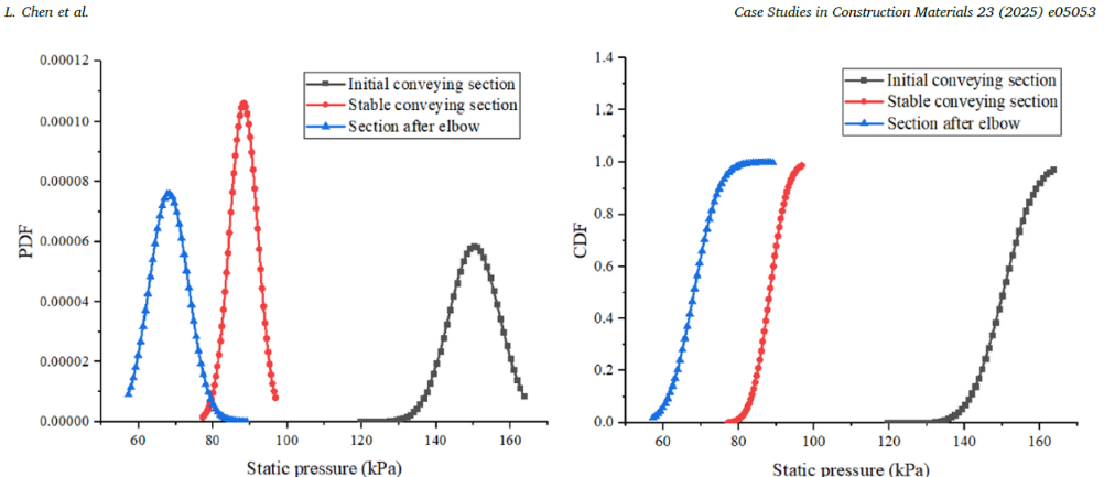
Figure 2. PDF and CDF diagrams of pressure signals at different stages of material transport
Shotcrete Pipe Diameter: Faster Material or Lower Pressure Loss?
When the flow feels slow, a common response is to use a smaller pipe so that the air moves faster. This approach can indeed increase material velocity. At an airflow rate of 475 m³/h, material in the straight section of the 51 mm pipe traveled at approximately 27 m/s, while material in the 70 mm pipe traveled at only around 18 m/s (approximate readings from the graph).
The trade-off is pressure. The diameter difference is only 19 mm between the smallest and largest pipes, yet the pressure loss is nearly two and a half times higher (Chen et al., 2025).
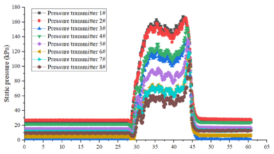
Figure 3. Pressure drop characteristics of stiff shotcrete materials (pipe diameter: 51 mm)
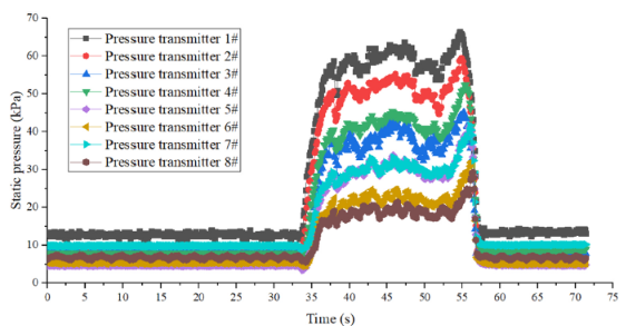
Figure 4. Pressure drop characteristics of stiff shotcrete materials (pipe diameter: 70 mm)
High velocity is not necessarily the goal. What matters is that the material reaches the nozzle in a stable and controlled flow. That depends on how much energy is lost along the way.
Pipe Bends Need to Be Considered During Planning
There are three practical points to consider in the field:
- Treat pipe bends as part of the design. Their number, location, and distance from the inlet should be considered, because fewer bends mean fewer opportunities for coarse aggregate to settle and then surge forward in waves.
- Measure pressure at several points, not only at the compressor. Compressor airflow alone does not explain what happens after the bends. Measurement points in the initial section, straight section, and downstream of the bend provide a more realistic picture. A sudden widening of the pressure distribution at a particular point could be an early sign of a developing blockage.
- Select pipe diameter as a balance. Velocity, pressure, and compressor load are interconnected. A smaller pipe increases material velocity, but the initial section and bends become more heavily loaded.
Study Limitations to Keep in Mind
- All experiments used a single mix composition (cement, sand, and aggregate at a ratio of 1 : 2.25 : 1.5, water-cement ratio of 0.3, maximum aggregate size of 10 mm) and three pipe sizes.
- The reported values should be read as trends, not universal design values for every mix and pipeline configuration.
- The study did not measure material rebound from the wall or the quality of the sprayed layer, so the effect on final concrete quality needs to be evaluated directly in the field.
Conclusion: Inspect the Whole Pipeline, Not Just the Mix
Intermittent shotcrete spray is often immediately blamed on the mix. But before the material reaches the rock surface, it has already traveled a long way: driven by compressed air, transported through the pipeline, and forced through bends that can reduce its velocity by 30–40%. If these points are not investigated, even a well-designed mix can arrive at the nozzle in a condition different from what was intended.
That is why APTEKINDO views ground support as an integrated chain from the compressor, pipeline, and bends all the way to the rock surface being supported. Strong ground support starts with material that arrives in the right condition.
Dealing with a pulsating shotcrete spray? Discuss your pipeline and material conditions with the APTEKINDO team.
Frequently Asked Questions (FAQ)
What causes a pulsating shotcrete spray?
It is not always the concrete mix. In this study, pipe bends made the material hit the wall and slow down by 30–40%, leaving coarse aggregate behind that then caught up in waves, so the spray at the nozzle felt pulsating.
Why is pressure loss higher at pipe bends?
Per unit length, pressure loss at the bend is roughly 2–3 times that of a stable straight section. In the initial section it is around 3–4 times.
Is a smaller shotcrete pipe better?
A smaller pipe makes material travel faster but causes much higher pressure loss. In this study, maximum pressure loss was about 150 kPa in the 51 mm pipe versus 60 kPa in the 70 mm pipe. Diameter should be chosen as a balance.
Where should pressure be measured?
At several points: the initial section, the straight section, and downstream of the bend, not only at the compressor. A sudden widening of the pressure distribution at one point can be an early sign before a blockage.
References
Chen, L., Liu, M., & Sun, Z. (2025). Experimental study on the pneumatic conveying characteristics of stiff shotcrete materials. Case Studies in Construction Materials, 23, Article e05053. https://doi.org/10.1016/j.cscm.2025.e05053
- Share